The Raspberry Pi is an extremely interesting invention. It is a full-fledged Linux box (literally can be caged inside a plastic box) and it basically allows you to run any program to connect to any other communicating device around it through cables or a Bluetooth adapter. I am going to show you how to build your own system to hook up a Raspberry Pi to your car, then extract diagnostic information from the CAN bus, upload that to the cloud, and then use a streaming API to predict who is driving the vehicle using a learning model created through a periodic backend process. To understand this, you need some basic electrical engineering skills and some exposure to Python programming.
Since all this work is pretty long, I intend to break it up into three parts which I am going to put into three different articles as follows:
- Driver Signatures from OBD Data captured using a Raspberry Pi: Part 1 (Building your Raspberry Pi setup)
- Driver Signatures from OBD Data captured using a Raspberry Pi: Part 2 (Reading real-time data and uploading to the cloud)
- Driver Signatures from OBD Data captured using a Raspberry Pi: Part 3 (Analyzing driver data and making predictions)
You should go through these articles in order. You are currently reading Part 1 of this series.
Building your Raspberry Pi setup
Note that there are several web-sites where people have described how to set up a Raspberry Pi for reading Onboard Diagnostic (OBD) data. So my article here is mostly a repetition. I created my setup by reading those articles and watching YouTube videos. You should do that too. The only difference between my article and their's is that I provide a motive for doing all this work and take it further - i.e. for creating driver signatures. The articles I have seen on other blog sites take you through the process of building a Raspberry Pi setup, but their story ends right there. In my case, that is just chapter one - and the more interesting work of uploading to the cloud and analyzing that data follows after that. For completeness sake, I thus have to describe a few things about the setup that pertains to hardware. Without that you cannot even start the project. So just follow along. If you the handyman type of guy (or gal), roll up your sleeves and build it. It is fun!
To cut the description short, here are a few articles describing the setup with enough pictures to get you started.
I started off by going through the first article given here. My car is slightly old, so I had no way of using the car's monitor for seeing the dashboard. So I decided to hook up an independent monitor with my Raspberry Pi that I can carry along with me as a "kit". Moreover, I needed to try out this setup on different cars and different drivers to build any meaningful model - so it was important for me to make my setup independent of any attachment to a vehicle. What I wanted was to hop on any car, start my system using the car battery, hook up my Raspberry Pi to the OBD's ELM 327 adapter using Bluetooth and run my program. So my setup is a bit different from the other guy's since I also needed to upload all that data on the cloud while the car was in motion. Remember, I said I want to do real-time prediction of the driver, so all data that is being generated has to go to the cloud in real-time (or near real-time) where we will apply a prediction step on a pre-built model to make the prediction.
Bill of Materials (Main Items)
Given below are the accessories you need to purchase for a complete setup. I am giving a picture of the items as well so that you can match it as closely as you can when you purchase them.
Raspberry Pi 3
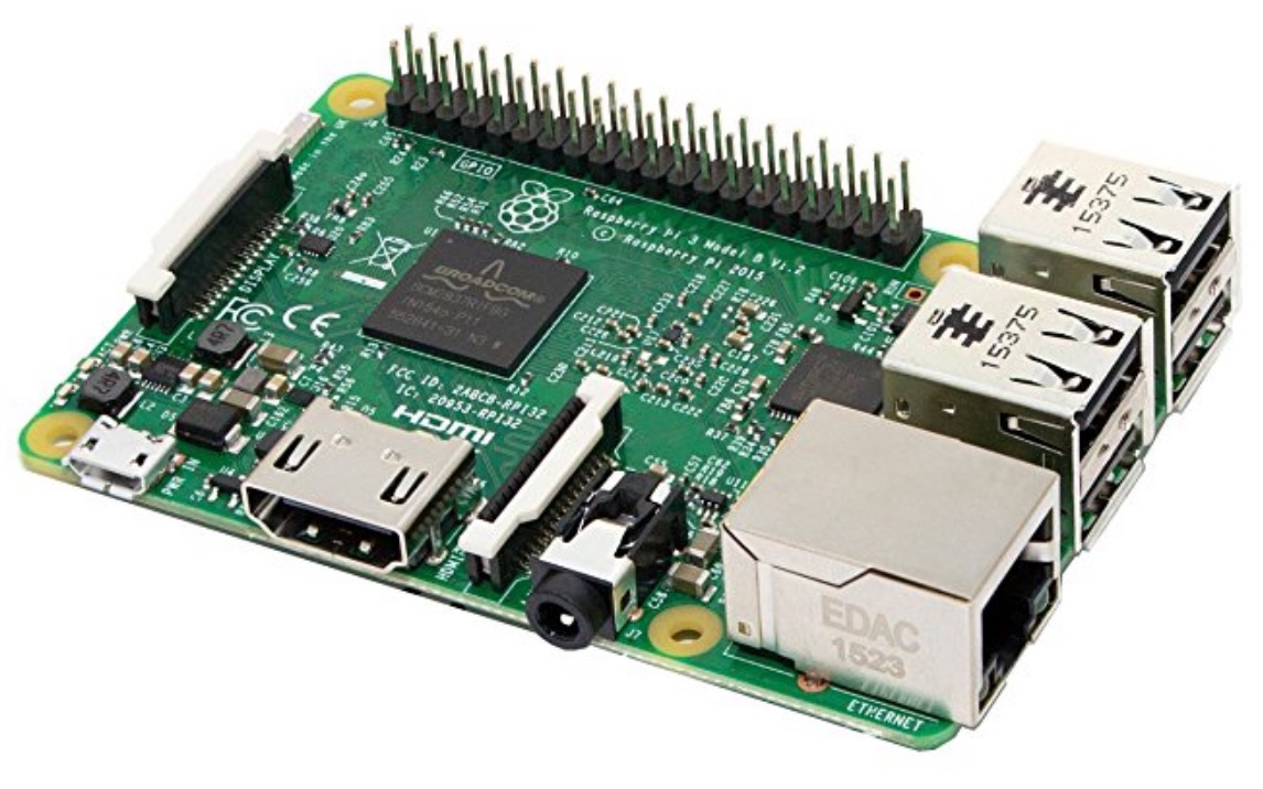
The first thing you want is a Raspberry Pi 3 computer. Here is how it looks. Search for one on web and purchase it from your country's online retailer.
You will also need to buy a plastic case for this board to protect the components.
Notice that the Pi shown above has an HDMI port for the monitor, an ethernet port, 4 USB ports and an SD card slot.
Monitor
You will need a 7-inch car monitor. Most people hook up the Raspberry Pi to the inbuilt monitor of the car, but my use-case is multi-car. So I wanted to keep my setup independent of any car - thus I went with a separate monitor. Here is what I used for this purpose.
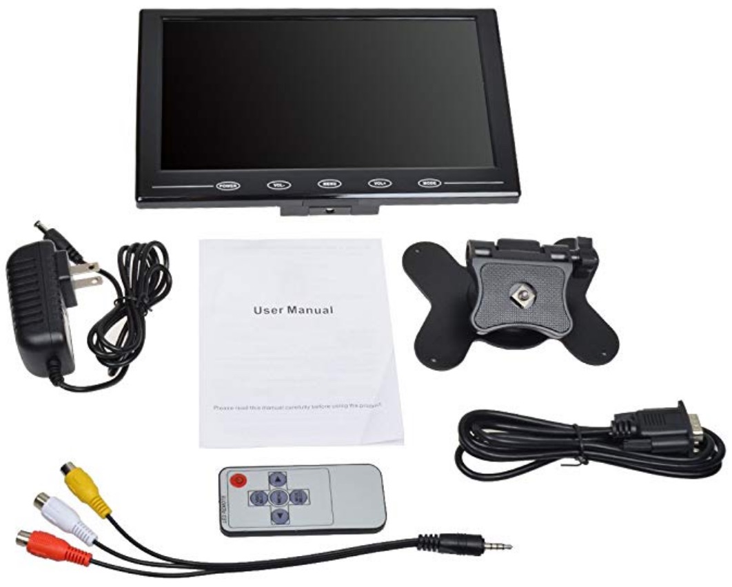
This does not come with an HDMI cable, so I had to purchase a separate cable myself to connect to the Pi. Note that this came with a 110V adapter, so you may choose to either buy a cable to use with your car's cigarette lighter slot, or buy an inverter that converts 12V DC to 110V AC and use that as your universal power source for all situations.
Inverter (Optional)
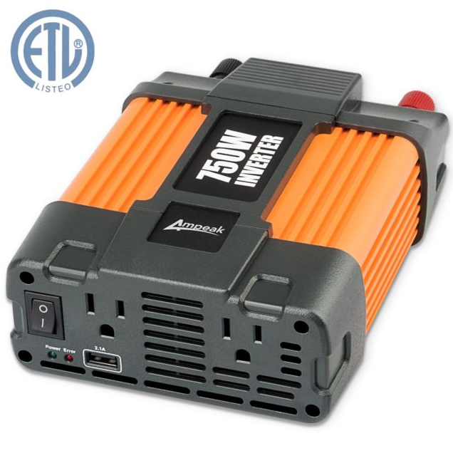
I decided to go with the DC to AC inverter since that also [1] acts as a spike buster in the car - (note that voltage spikes when you start the car), and [2] you can have just one setup for your power source needs, whether you are inside the car, or sitting in the lab for your post-processing or development needs.
Here is a picture of the inverter I am using:
Keyboard
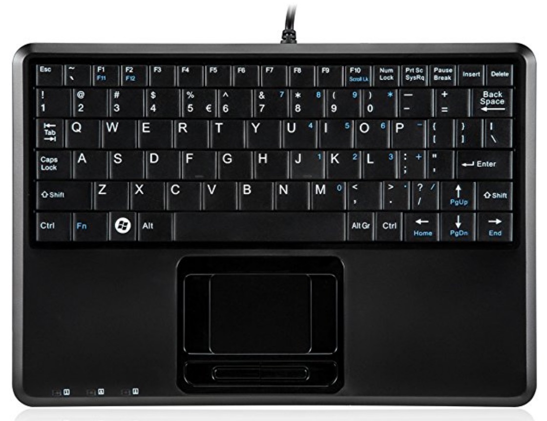
The next accessory you need is a keyboard to operate your machine. I went with an integrated keyboard/trackpad that goes along with size of the Raspberry Pi. Here is what I liked:
ELM 327 Adapter
To connect to your car, your Raspberry Pi needs a Bluetooth adapter. The ELM 327 standard allows a serial connection your car's CAN bus. This adapter can access your car's CAN bus data via a serial connection. Note that this is a slow connection (being serial), but we will try to manage with this. The connector is pretty cheap (around USD 10 or so). I have seen more advanced connectors from Kvaser that come in the range of $300 or so, and can read data at a much faster rate. Our connector will be able to read data at a reasonable rate, but not fast enough for highly accurate readings. We will live with it.
Here is how it looks.
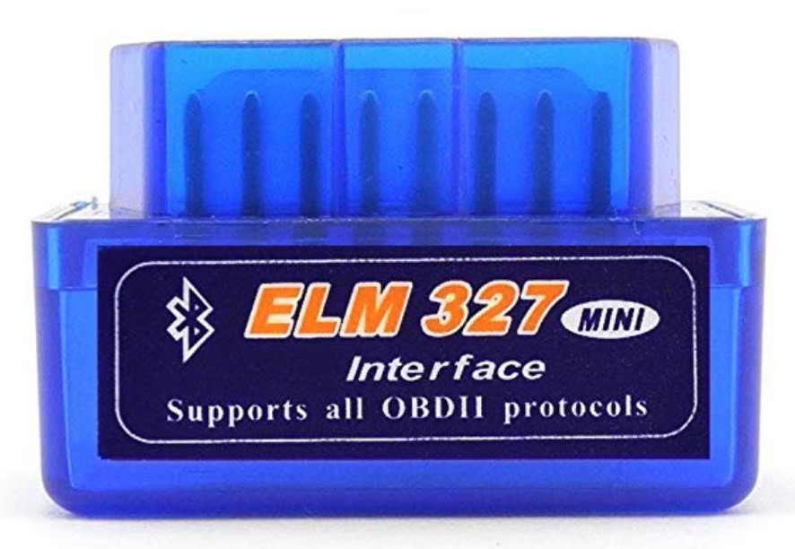
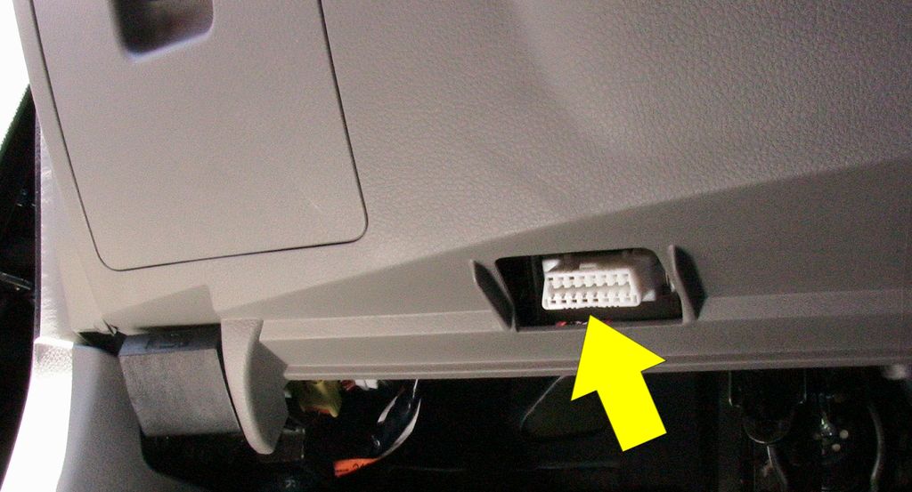
You need to insert this into your car's OBD2 port which is generally found under the steering wheel of your car. It is generally above your left foot, and the port looks like this.
GSM modem
Since we intend to upload our data to the cloud in real-time, we will need a GSM modem. There are many choices and the software setup is different for different vendors. I went with a TELUS modem that uses a Huawei chip internally.
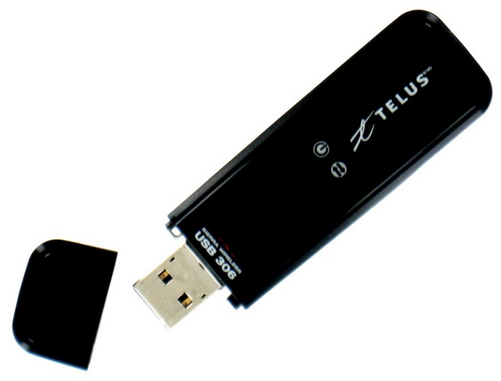
You will notice that this is where our setup goes beyond the other setups found on the internet.
GPS Antenna
Another important component we need is the GPS antenna. This is not really necessary for the driver signature part, but it is very important for visualization of data and to do other kinds of analysis - like speed and acceleration calculations from GPS data. Here is one that goes with the Raspberry Pi.
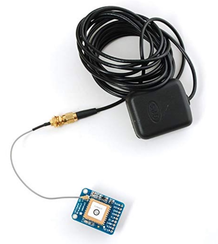
You need to follow the manual for connecting this to your Raspberry Pi. I had to do some soldering work in order to make the right connections. The software to drive this also needs to be installed via a 'apt-get' command.
Complete Kit
My complete kit after putting together all the components looks like this:
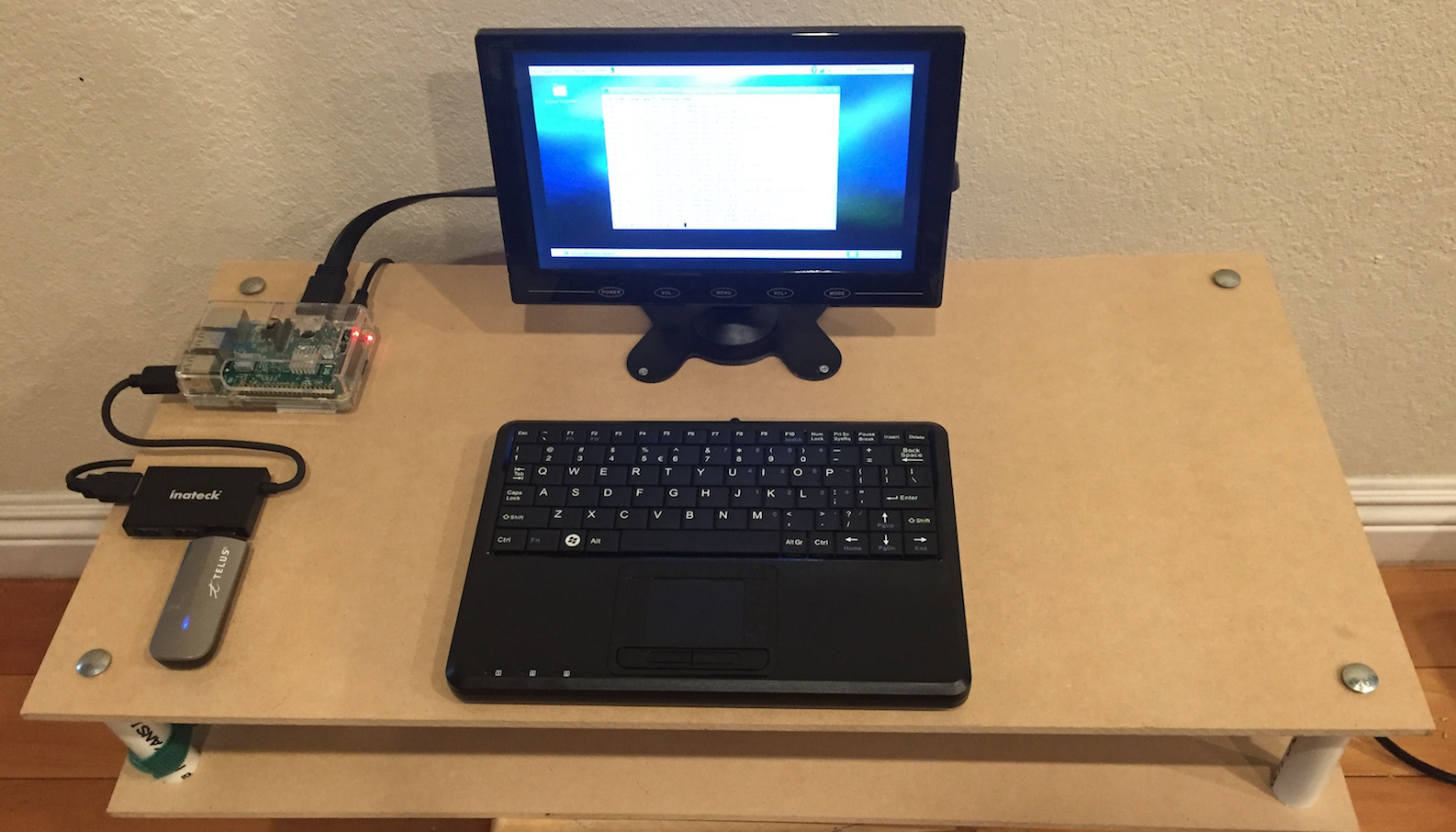
You can see that I decided to mount all of this on a two-layered particle board separated with plastic pipes. Even though it looks big, it is not clunky. There is enough room for expansion. I kept it in two layers so that all the power cables are hidden underneath the top board and exist out of view. You will need some velcro strips to keep the power supply units from falling away. I also used a USB extender (Inateck) to keep my USB devices from clogging up room around the Raspberry Pi.
This setup is clean and portable. You can use it to work and debug code inside your car or in the lab.
Conclusion
My setup was inspired by many articles on the web and on YouTube. You should also consult other links that show you how to do it. However this is not the main focus of this series - my main objective is to use this setup for some data science purpose. I chose to use this for driver signature analysis. The following two articles will delve deeper into the software setup - both on the client side and the server side, to solve this problem. You will find the links to the next two articles under. Happy reading!


